Thermal relay is generally composed of heating element, control contact and action system, reset mechanism, setting current device and temperature compensation element. When the deformation reaches a certain distance, the connecting rod will be pushed to open the control circuit, so that the contactor will lose power and the main circuit will be disconnected, thus realizing the overload protection of the motor.

In the actual operation of the motor, such as dragging the production machinery to work, if the machine is abnormal or the circuit is abnormal, the motor will encounter overload, the motor speed will decrease, the current in the winding will increase, and the winding temperature of the motor will increase. If the overload current is small and the overload time is short, and the motor winding does not exceed the allowable temperature rise, the overload is allowed. However, if the overload time is long and the overload current is large, the temperature rise of the motor winding will exceed the allowable value, aging the motor winding, shortening the service life of the motor, and even burning the motor winding in serious cases. Therefore, this kind of overload is the motor can not bear. Thermal relay is to use the thermal effect principle of current to cut off the motor circuit in case of overload that the motor can not bear, so as to provide overload protection for the motor.

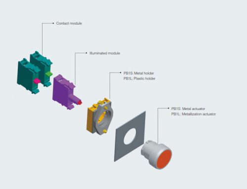
Working principle diagram of thermal relay
When the thermal relay is used for overload protection of the motor, the thermal element is connected in series with the stator winding of the motor, the normally closed contact of the thermal relay is connected in series in the control circuit of the electromagnetic coil of the AC contactor, and the adjusting knob of the setting current is adjusted to make the herringbone shift rod and the push rod at a proper distance.
When the motor works normally, the thermal element is heated by the current of the thermal element, that is, the rated current of the motor. The bimetallic sheet is bent after being heated, so that the push rod just contacts with the herringbone shift rod, but cannot push the herringbone lever. At this time, the normally closed contact is in the closed state, the AC contactor is kept closed, and the motor operates normally.
If the motor is overloaded, the current in the winding increases, and the current in the thermal element also increases, the temperature of bimetallic sheet rises higher, and the bending degree increases. It pushes the herringbone shift rod, which pushes the normally closede contact, so that the contact is disconnected, resulting in the disconnection of the AC contactor coil circuit, the contactor release and cut off the power supply of the motor, and the motor is protected by stopping.

1 – Current regulating cam, 2 – Leaf spring (2a, 2b), 3 – Manual reset button, 4 – Bow spring, 5 – Main metal sheet, 6 – Outer guide plate, 7 – Inner guide plate, 8 – Normally closed static contact, 9 – Moving contact, 10 – Lever, 11 – Normally open static contact (reset adjusting screw), 12 – Compensating bimetallic sheet, 13 – Push rod, 14 – Connecting rod, 15 – Press spring
Thermal element
Thermal element is the heart of thermal relay:
1. Direct heating type thermal relay is to use bimetallic sheet as thermal element to let electric sulfur pass through directly. Because the bimetallic sheet itself has a certain resistance, it can generate heat when the current passes through it. Because bimetallic sheet is used as both sensing element and heating element, this heating method has the characteristics of simple structure, small volume, saving material, small heating time constant and rapid temperature change.
2. Indirect heating is the generation of heat through a thermal element that is electrically unconnected with the bimetallic sheet. The thermal elements are filamentous or banded around the bimetallic sheet. Because the heat generated by the thermal element is transmitted to the bimetallic sheet through the air, the heating time constant is large and the rate reflecting the temperature change is relatively slow.
3. Compound heating is actually a combination of direct heating and indirect heating. The heating time constant of compound heating is between the above two forms. The resistance value can be easily adjusted by parallel or series connection of different resistances, and it has the advantages of direct heating and indirect heating, so it has been widely used.
4. Current transformer heating is mainly used for large capacity thermal relay and heavy load starting thermal relay.

Control contact and action system
At present, the widely used structure of thermal relay is spring type moving contact. When the motor is overloaded, the normally closed contact will be disconnected. After the motor stops, the bimetallic sheet of thermal relay will be cooled and reset. The moving contact of normally closed contact will reset automatically under the action of spring. However, the traditional spring type moving contact spring is easy to fall off, causing the auxiliary contact is not electrified, resulting in the thermal relay can not be used. The existing safer method is to upgrade the spring type moving contact to the leaf spring type dynamic contact, and set the contact bridge into the leaf spring type contact bridge, so that the vibration of the moving contact is greater when it contacts with the static contact. Due to the influence of the motion inertia and collision, the spring type contact bridge will produce dynamic elastic deformation. At different dynamic moments, the original flat leaf spring contact bridge will have different and curvature produces bending and extension movement, which further drives the spherical moving contact to produce friction rolling relative to the static contact, which makes the surface membrane resistance more fully damaged, ensures the contact conduction effect and improves the reliability of the equipment.

Reset mechanism and open phase protection
After the thermal element is heated and bent, the main circuit current is cut off by pushing the starting device to make the thermal relay act. The bimetallic sheet is cooled while restoring its original state. Obviously, it takes time. There are two ways to reset the thermal relay, manual and automatic. Manual reset is generally not less than 5min, automatic reset is not more than 10min.
The reset mode can be selected by the reset button. In normal state, when the reset button points to A (automatic reset), NC is closed and NO is disconnected; in tripping state, when the reset button points to A, NC is opened and NO is closed. After the motor is cut off and stopped, the moving contact cannot be reset. The moving contact can be reset only after pressing the reset button. At this time, the thermal relay is in manual reset state. If the motor overload is fault, in order to avoid starting the motor easily again, the thermal relay should adopt manual reset mode. In manual reset state, the principle of reset is the same. To change the thermal relay from manual reset mode to automatic reset mode, just turn the reset button to A (automatic reset).
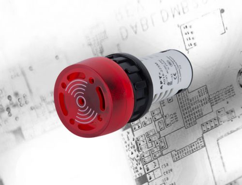
Some types of thermal relays also have open phase protection. The structure diagram is shown in the figure below. The open phase protection function of thermal relay is provided by differential amplification mechanism composed of inner and outer push rods. When the motor works normally, the current of the thermal element through the thermal relay is normal, and both the internal and external push rods move forward to the appropriate position; when the power supply phase is broken, the phase current is zero, and the bimetallic sheet of the phase is cooled and reset, which makes the inner push rod move to the right, and the bimetallic sheet of the other two phases increases the bending degree due to the increase of current, which makes the outer push rod move to the left The differential amplification function pushes the normally closed contact to open in a short time after the phase failure occurs, so that the AC contactor is released and the motor is protected by power failure.

Setting current device and temperature compensation
The setting current refers to the maximum current that passes through the heating element for a long time without the release of the thermal relay. When the current passing through the heating element exceeds 20% of the setting current value, the thermal relay shall act within 20 minutes. The setting current of thermal relay can be changed by setting current knob. When selecting and setting the thermal relay, the setting current value must be consistent with the rated current of the motor.
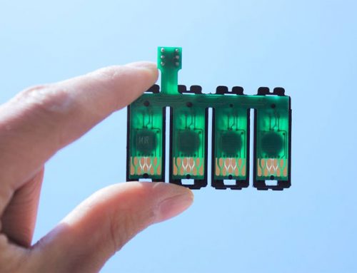
A high precision current setting structure of thermal overload relay includes a support (1), a compensating double gold (3), an adjusting screw (4) and a setting cam (5).

Thermal overload relay is the most widely used electrical component for motor protection. In the process of use, the customer needs to adjust the setting current value of the thermal overload relay according to the actual working condition of the motor. If the setting accuracy of thermal overload relay is not high, it is easy to cause abnormal shutdown or overheat burning of the motor.
The left arm of the herringbone shift rod is also made of bimetallic sheet. When the ambient temperature changes, the bimetallic sheet in the main circuit will deform and bend to a certain extent. At this time, the left arm of the herringbone shift rod will also deform and bend in the same direction, so as to keep the distance between the herringbone lever and the push rod basically unchanged, so as to ensure the accuracy of thermal relay operation. This effect is called temperature compensation.

We can see from the figure below how to solve the problem of low current overall accuracy of traditional structure by compensating double gold.

Riveting hole and threaded hole are set on the compensation double metal. The riveting hole is matched with the riveting boss, and the threaded hole is connected with the adjusting screw thread. On the compensation double metal, the feature hole matched with riveting boss is designed, so that the compensation double metal and U-shaped parts are riveted and fixed.
Under the action of the support step plane and hot riveting forming characteristics, the compensation double gold component ensures the positioning accuracy, thus improving the current setting accuracy caused by setting cam operation, and solves the problem of low current setting accuracy of traditional structure.